

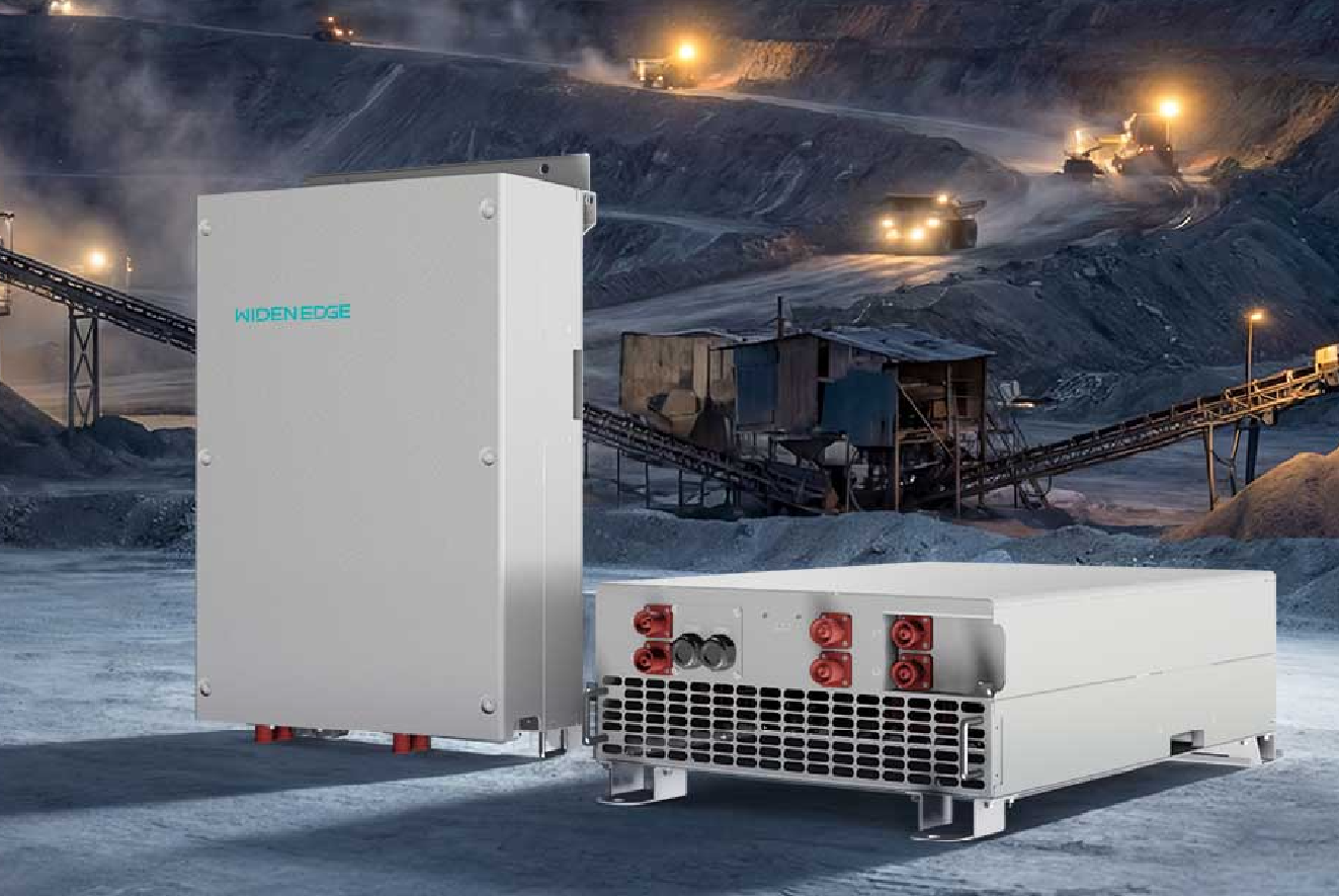
Problem statement and immediate constraints
Containerized energy storage projects demand high continuous power, repeatable start/stop behavior, and compact thermal envelopes. Scaling a single-module concept up to a 600 kW inverter creates three urgent problems: heat density, fault tolerance, and predictable grid interactions. A common commercial stepping stone is the 125kW commercial energy storage inverter, which clarifies how module-level choices propagate when you multiply capacity inside a container. Addressing these problems requires deliberate architectural decisions rather than incremental tweaks.
Technical objectives that must drive design choices
Set measurable targets before selecting components. Clear objectives stop scope creep and focus engineering tradeoffs.
– Deliver 600 kW continuous at rated ambient conditions with N+1 redundancy for critical subsystems.
– Keep total harmonic distortion below grid-code limits while supporting fast ramp rates.
– Ensure mean time between failures (MTBF) exceeds typical utility expectations and simplify on-site service.
– Maintain a workable container thermal budget using liquid or directed-air cooling.
– Achieve type-test compliance and a predictable certification path.
Field tests of the chosen sic inverter during a utility-scale deployment in California provided practical loss and thermal benchmarks that informed cooling and switching-frequency choices.
Architecture and topology decisions
Pick an architecture that isolates faults and permits staged scaling. Modular string inverters or multi-module rack architectures simplify service and lower single-point failure risk.
Key design patterns:- Distributed power stages: multiple 100–150 kW power blocks allow graceful degradation and reduce specialized spare stock.
– Medium-voltage DC bus with isolated DC/DC or transformer coupling to match battery pack voltage and reduce I2R losses.
– SiC-based wide-bandgap semiconductors to reduce switching and conduction losses at higher frequencies (helps reduce passive component size).
– Parallel cooling zones inside the container to avoid hot spots and enable targeted maintenance.
Thermal engineering and reliability practices
Thermal choices determine serviceability and component life. Higher switching frequencies reduce passive size but raise thermal density; choose where to pay the penalty.
Practical methods:- Use conduction-cooled power modules mounted to cold plates for repeatable thermal interfaces.
– Prefer liquid cooling for the highest-density racks, but design failsafe air-cooling paths for forced-air redundancy.
– Specify accelerated life testing for capacitors and fans; monitor electrolyte capacitors for early replacement windows.
Common mistakes to avoid:- Underestimating thermal interface resistance between module and cold plate.
– Locking in a single cooling supplier without cross-qualified backups.
– Designing for nominal ambient only—account for container solar loads and reduced ventilation at higher elevations.
Control, protection, and grid integration
Control firmware is where reliability and compliance converge. Favor deterministic control stacks and simple, auditable protection logic.
Essential control capabilities:- Fast current control loop with configurable ride-through behaviors and adaptive anti-islanding.
– Active/reactive modulation and ramp-rate limits that meet local interconnection standards.
– Fault logging and telemetry designed for rapid fault isolation and firmware rollback.
Pitfalls: overloading the control processor with noncritical features; delaying thorough type tests for LVRT and harmonics until late in the project.
Testing, certification, and manufacturability
Testing strategy shortens time to market. Validate early with module-level power cycling and full-system type tests that mimic container conditions.
Recommended sequence:- Component validation: power devices, capacitors, thermal interfaces.
– Module stress: thermal cycling and partial-discharge or insulation testing where applicable.
– System-level tests: EMC, LVRT, frequency response, and accelerated life with battery emulators.
Manufacturing notes: design for testability—use removable racks, standardized connectors, and clear in-container service access to reduce field MTTR.
Alternatives and trade-offs
Every choice has a cost. Compare realistic alternatives to focus decisions.
– IGBT-based designs: lower device cost, lower max switching frequency, larger passive components, often simpler thermal paths.
– SiC-based designs: higher upfront device cost, smaller magnetics and capacitors, improved efficiency at high switching frequency—beneficial when container space is limited.
– Centralized vs. distributed architectures: centralized reduces duplication but increases single-point failure risk; distributed simplifies spares and phased commissioning.
Synthesis and practical outcome
Design a 600 kW container inverter by defining measurable objectives, partitioning power into serviceable modules, and choosing cooling and semiconductor strategies that match those objectives. Prioritize deterministic control and early, realistic testing to reduce surprises during certification. These steps produce predictable performance and maintainability, consistent with long-term deployments and system integrators such as WidenEdge.